Close
Your shopping cart is empty


An antenna may look like a small component, but it directly affects how reliably a wireless device transmits and receives signals. A model that matches the nominal frequency may still perform poorly when the gain, radiation pattern, connector, cable, enclosure, or installation location does not fit the application.
This guide explains how engineers, product managers, and buyers can review the main selection factors before choosing a standard antenna or starting a custom antenna project. It does not replace device-level RF testing; instead, it helps teams prepare the information needed for a more efficient technical evaluation.
The first technical question is usually, “Which frequency does the device use?” This is essential because an antenna must cover the intended operating band. However, two antennas covering the same band can behave very differently after they are integrated into a product.
Important differences may include antenna type, nominal gain, radiation pattern, polarization, size, connector, cable loss, mounting method, and sensitivity to nearby metal or electronic components. The operating environment also matters. A stationary outdoor gateway, a vehicle-mounted radio, a compact IoT sensor, and a Wi-Fi access point may all require different antenna structures even when part of their frequency coverage overlaps.
For this reason, frequency matching should be treated as the first screening condition—not the final purchasing decision.
Start with the wireless module, radio, or communication standard used by the device. Record every band that the finished product must support rather than providing only a general description such as “5G antenna” or “Wi-Fi antenna.” Market-specific deployments can use different bands, so the target countries or regions should also be identified.
When several radio systems are used in one product, the team should also confirm whether they will use separate antennas or an integrated antenna configuration. This decision affects available space, isolation, cable routing, and the testing plan.
Antenna gain describes how strongly an antenna concentrates energy in particular directions compared with a reference. It should not be interpreted as a simple “more is always better” score.
A higher-gain antenna generally concentrates coverage into a narrower pattern. This can be useful when the target signal direction is known, such as a point-to-point installation. However, a broad coverage pattern may be more appropriate when users, devices, or signal sources can be located in many directions.
When a supplier lists a gain value, buyers should also ask whether it is a nominal or typical value and review available radiation-pattern or test information when the project requires it.
The physical antenna type often reflects how and where the product will be installed. The following comparison provides a practical starting point; the final selection still requires review against the actual device and environment.
| Antenna type | Coverage characteristic | Typical selection consideration |
|---|---|---|
| Omnidirectional | Designed to provide coverage around the antenna | Useful when devices or signal sources may be located in different horizontal directions |
| Panel | Directs energy mainly toward one side | Suitable when coverage needs to be focused toward a defined area |
| Yagi | Directional coverage | Often considered for fixed links or when the direction of the target signal is known |
| Patch | Compact directional structure | Commonly evaluated for embedded or surface-mounted applications, depending on the frequency and ground conditions |
| Magnetic or roof mount | Defined by installation hardware and position | Frequently considered for vehicles, temporary installations, or installations that require an external antenna |
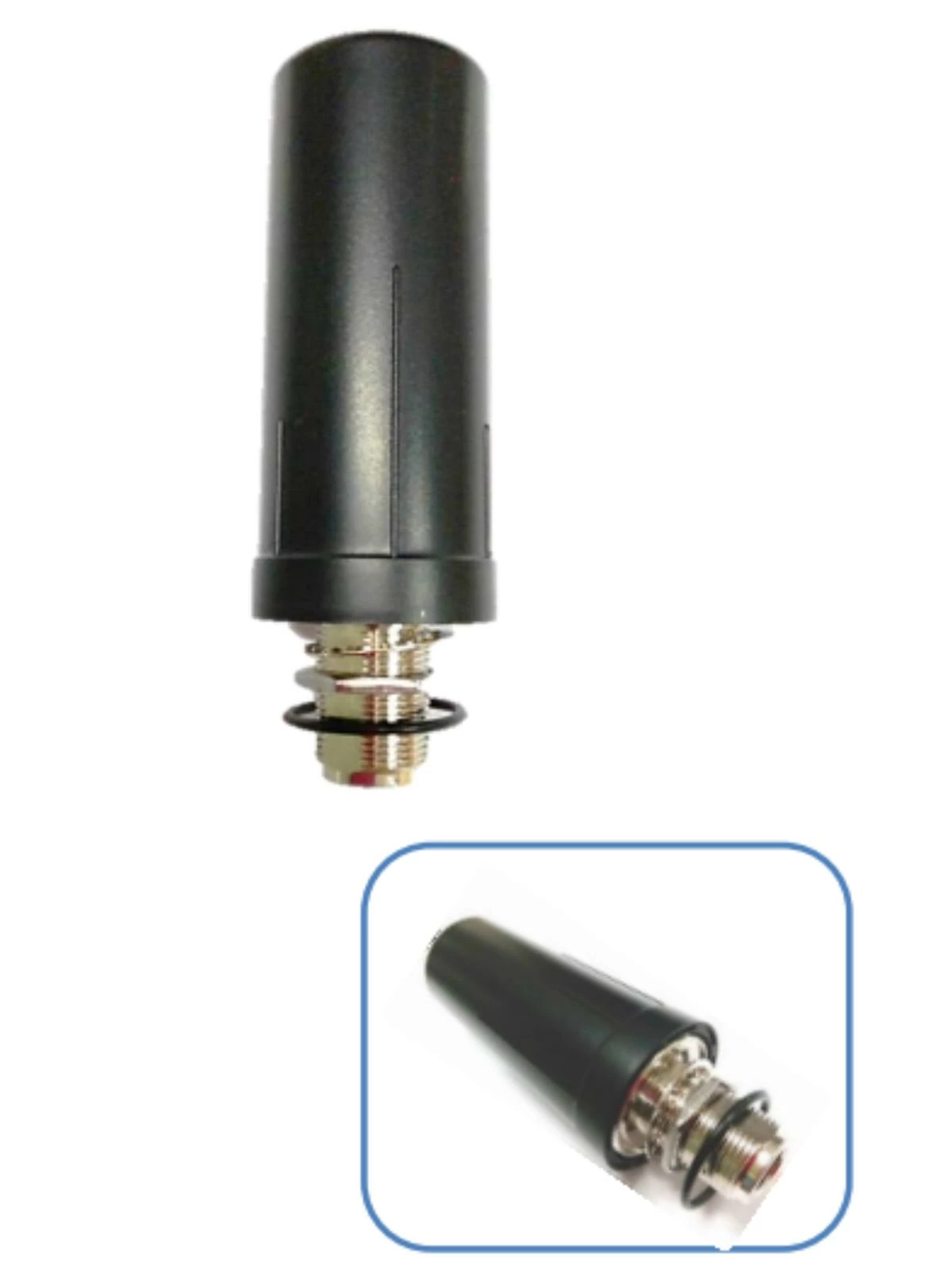
Mounting position can be as important as the antenna itself. Nearby metal, walls, equipment, the device enclosure, and human interaction may change the effective radiation pattern. A good catalog match should therefore be followed by evaluation in the intended installation.
The connector must match the radio equipment mechanically and electrically. Common antenna products may offer SMA, RP-SMA, N-type, FME, TNC, BNC, MMCX, MCX, or other connector options, but the exact choice depends on the device interface and installation.
Cable length and cable type also affect the RF path. A longer cable can make installation easier but introduces additional loss. Instead of selecting cable length solely for convenience, confirm the actual routing distance, allowable bending, connector access, and frequency range. Cable and connector choices should be documented in the approved sample to avoid errors during production.
An antenna does not operate in isolation. Plastic housings, metal structures, batteries, displays, PCBs, cables, and other antennas can alter its performance. For embedded designs, the available clearance and ground conditions should be reviewed early, before the mechanical layout is fixed.
External antennas require a different set of questions:
Environmental protection levels, test conditions, and material requirements must be confirmed for the specific antenna model. They should not be assumed from product appearance alone.
A standard antenna is often the fastest route when its frequency, dimensions, gain, connector, cable, and mounting method already fit the product. It can be useful for early prototypes, replacement projects, and applications with flexible mechanical space.
Customization may be appropriate when the project requires a different connector or cable, restricted dimensions, multiple frequency bands, integration into a specific enclosure, a unique mounting method, or performance optimization in the finished device.
| Project condition | Standard antenna may fit | Customization may be needed |
|---|---|---|
| Frequency and gain | Existing specifications cover the application | Required bands or performance cannot be met by available models |
| Mechanical space | Installation space is flexible | Device dimensions or antenna position are restricted |
| Connector and cable | Standard options match the device | Special connector, cable, length, or routing is required |
| Product integration | Antenna is externally installed with limited interaction | Antenna must be optimized with the enclosure, PCB, or other radios |
Evercom states that its business has developed from OEM toward ODM and JDM and that it has created more than 500 customized items. Learn more about its stated development approach on the Evercom company profile.
A complete RFQ helps the supplier determine whether a standard product is suitable and what must be confirmed before customization. If some data is not yet available, identify it as pending instead of replacing it with an assumption.
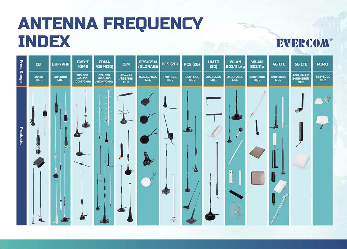
Buyers can first use Evercom's product categories and antenna frequency index to review available options, then submit the actual device requirements for confirmation.
No. Higher gain generally concentrates energy more strongly in certain directions. The appropriate gain depends on the required coverage pattern, installation, cable loss, and radio system.
Frequency matching is essential, but it is not sufficient. Antenna type, gain, polarization, connector, cable, available space, enclosure, mounting position, and environment should also be reviewed.
The PCB, ground conditions, housing materials, nearby metal, cable routing, antenna position, and other components can change the RF environment. Finished-device testing is therefore important.
Customization may be needed when standard models cannot meet the required bands, dimensions, connector, cable, mounting, or device-integration conditions.
Provide the application, frequency bands, device or module information, dimensions, mounting method, connector, cable, environment, quantity, schedule, and any required validation documents.
A suitable antenna is not selected by one specification alone. Frequency, gain, radiation pattern, antenna type, connector, cable, enclosure, mounting, and the operating environment work together. Reviewing these factors early helps reduce unsuitable samples and makes communication between engineering and purchasing teams more efficient.
Explore Evercom's antenna product range or contact Evercom with your device and RF requirements for further product confirmatio