Close
Your shopping cart is empty


Connected vehicles, asset trackers, industrial gateways, telemetry terminals, fleet devices, and remote IoT systems often need both positioning and wide-area data communication. This usually means combining a GPS/GNSS signal path with a 4G or 5G cellular path. Although both functions may be housed in one product, their radio roles, installation requirements, and validation methods are different. A reliable design begins by defining the complete architecture rather than choosing an antenna only by appearance.
GNSS is a general term for satellite navigation systems. GPS is one GNSS constellation, while a receiver may support additional constellations depending on the module and application. The antenna receives very weak signals arriving from satellites, so a clear view toward the sky, appropriate orientation, low-loss signal path, and control of nearby interference are important.
The cellular antenna performs a different task. It transmits and receives through a mobile network across the bands supported by the modem and target operator. Coverage requirements may differ by country, module, and generation of service. A design may use a single cellular path or multiple cellular antennas for diversity or MIMO, depending on the modem architecture.

A typical connected device therefore contains at least two functional chains: the GNSS antenna connected to the positioning receiver, and the cellular antenna connected to the modem. The product may also include Wi-Fi, Bluetooth, or other radios. Each path needs the correct connector and cable, but the complete set must also be evaluated for spacing, isolation, coexistence, installation, and assembly.
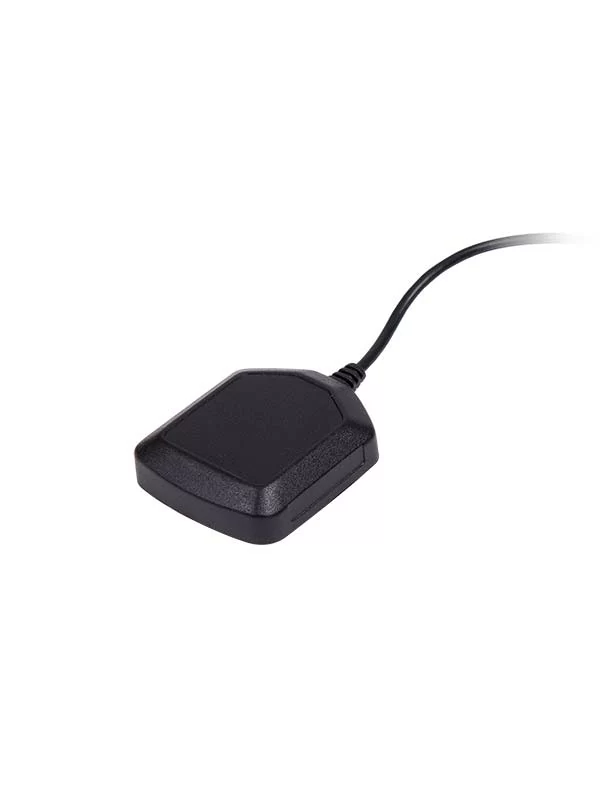
A passive GNSS antenna contains the radiating element without an integrated low-noise amplifier. It can be appropriate when the antenna is close to the receiver, the signal path is short, and the receiver architecture is designed for a passive antenna. Because there is no integrated amplifier, the receiver and installation must provide a suitable link budget.
An active GNSS antenna combines the antenna element with amplification electronics, typically including a low-noise amplifier. The receiver normally supplies DC power through the RF connection if it supports an active antenna. This architecture is often considered when cable length or installation distance would otherwise add loss, but compatibility must be confirmed.
Active is not automatically better, and passive is not automatically simpler. The correct choice depends on the receiver, cable, installation distance, surrounding radios, available power, and validation plan.
The cellular antenna must cover the bands required by the selected modem, operators, and deployment markets. A label such as “4G” or “5G” alone is not enough to confirm suitability. The engineering team should identify the actual bands, whether multiple cellular antenna ports are required, and how the antenna will be mounted in the final equipment.
For a vehicle or remote IoT device, cellular performance can be affected by the bodywork, enclosure, mounting surface, cable path, modem location, and the relative position of the GNSS and other antennas. A roof-mounted antenna may have a different ground-plane environment from a dashboard, glass, magnetic, adhesive, or internal installation.
When the modem supports diversity or MIMO, each required port should be connected to an appropriate antenna path. Spacing and orientation need to be considered as part of the product design. Leaving a required port unused or placing antennas too close without evaluation may reduce the intended system benefit.
A separate architecture uses individual GNSS and cellular antennas. A combination antenna integrates two or more functions into one housing while retaining separate RF connections internally. Neither approach is universally superior.
| Architecture | Potential advantages | Points to evaluate | Typical fit |
|---|---|---|---|
| Separate antennas | Independent placement, easier optimization of each path, flexible replacement, and wider choice of existing products. | More mounting points, more cable routing, visual impact, assembly time, and required spacing. | Devices with enough space or applications where each radio needs a different location. |
| Combination antenna | Fewer external housings, simplified appearance, consolidated installation, and organized cable exits. | Internal isolation, housing size, cable identification, connector mapping, serviceability, and combined environmental sealing. | Vehicles, gateways, kiosks, and IoT equipment where a compact installation is important. |
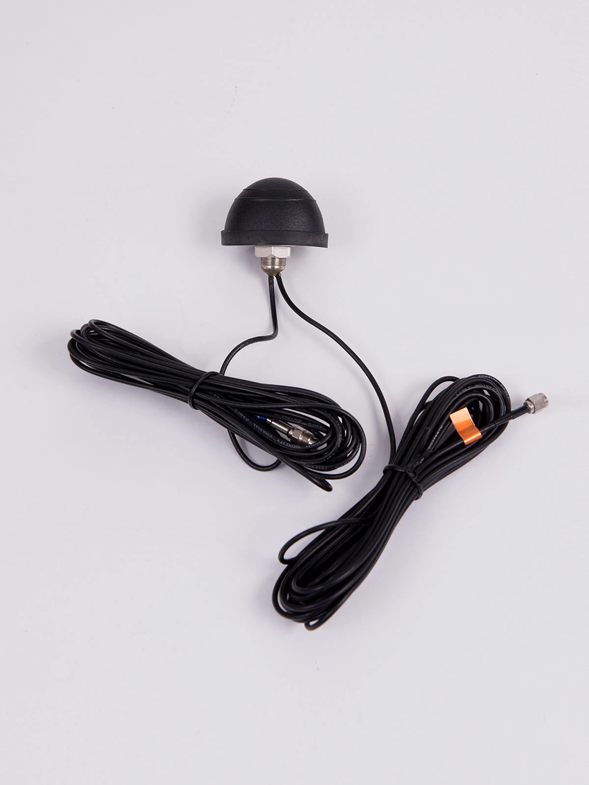
A combination housing does not mean the RF paths are interchangeable. Each cable and connector must be identified correctly and connected to the corresponding modem or GNSS port. Installation instructions, labeling, connector keying, and cable colors can help reduce assembly errors.
Installation is often the largest difference between a satisfactory antenna and an unreliable system. GNSS generally benefits from an unobstructed view toward the sky. Cellular coverage depends on the desired radiation around the device and on the surrounding conductive structure. The best position for one path is not always the best position for the other.
| Installation approach | Advantages | Engineering checks |
|---|---|---|
| Roof or external surface | Potentially clearer sky view and reduced shielding from the enclosure. | Ground plane, sealing, drilling or fastening, cable entry, vehicle clearance, and service access. |
| Magnetic mount | Fast installation and repositioning on a suitable metal surface. | Surface compatibility, retention, cable protection, movement, and the effect of the mounting surface. |
| Adhesive or glass mount | Can avoid drilling and support discreet installation. | Glass coatings, adhesive durability, orientation, cable exit, temperature, and nearby metal. |
| Internal installation | Protection from direct exposure and cleaner external appearance. | Enclosure attenuation, metal shielding, battery and PCB location, available clearance, and repeatable assembly. |
For a vehicle, consider the antenna position across the full installation population, not just one prototype. For an IoT enclosure, define the orientation in actual use. A device installed vertically on a pole, horizontally inside a cabinet, under a dashboard, or against a metal wall may exhibit different coverage.
Cable and connectors are part of the RF system. A longer cable increases loss, especially as frequency rises. Extra adapters and poorly controlled routing add additional uncertainty. The antenna specification and sample request should therefore state the exact connector, cable type, length, exit direction, and any retention or waterproofing needs.
Do not assume that two visually similar connectors are electrically or mechanically interchangeable. The mating part, module documentation, and complete cable assembly should be confirmed before ordering samples.
Vehicles and remote IoT systems can experience temperature change, vibration, moisture, dust, ultraviolet exposure, cleaning agents, and mechanical stress. The buyer should define the actual installation environment and required validation rather than assuming that every external antenna meets the same conditions.
The required test standard or acceptance method is determined by the final product and buyer's validation plan. Share these requirements before design selection so the antenna housing, cable entry, connector, and mounting method can be reviewed together.
A complete RFQ allows the supplier to recommend an architecture instead of guessing from a generic request. Include the following information:
Clearly separate mandatory requirements from preferences. If the antenna supplier is allowed to recommend the mounting position, cable, or architecture, state that in the request and provide the constraints needed for an engineering proposal.
GPS is one satellite navigation constellation. GNSS is the broader term for satellite navigation systems. The receiver module determines which constellations and bands are supported, so the antenna must be matched to the intended receiver architecture.
Not necessarily. A combination housing commonly contains separate antenna paths with separate cables or connectors for GNSS, cellular, and other radios. Each path must be identified and connected to the correct equipment port.
It may be considered when the receiver supports bias power and the signal path or cable length benefits from integrated amplification. Voltage, current, cable loss, filtering, and receiver compatibility must all be confirmed.
The conductive mounting surface can significantly affect an antenna. Whether the effect is beneficial depends on the antenna design and intended ground plane. Use the specified mounting method and verify performance on a representative installation.
Confirm antenna matching and radiation as required, GNSS acquisition and positioning behavior, cellular connection across relevant bands and orientations, coexistence with other radios, cable and connector integrity, and the environmental or mechanical checks defined for the product.
A GPS/GNSS plus 4G/5G system should be treated as an integrated product. The correct solution depends on receiver and modem ports, frequency coverage, active or passive GNSS architecture, separate or combination housing, mounting surface, cable, connector, environment, and final-device testing.
Browse Evercom's GPS antenna range, review the GPM-10 GPS/cellular combination antenna, explore multi-antenna solutions and automotive applications, or contact Evercom with your device architecture and installation requirements.