Close
Your shopping cart is empty


Choosing an antenna supplier is not only a matter of comparing catalog specifications. When a standard antenna cannot meet the available space, enclosure, connector, cable, installation, or target-market requirements, the project becomes an engineering collaboration. Buyers then need to understand what OEM, ODM, and JDM services include, what information should be prepared, and how a custom antenna moves from an initial request to approved production.
The three service models are related, but they are not interchangeable. The practical difference is how design responsibility and intellectual input are divided between the buyer and the supplier.
| Service model | Typical starting point | Supplier role | Best suited to |
|---|---|---|---|
| OEM | The buyer provides a defined design, specification, drawing, or approved sample. | Manufacturing, process planning, quality control, and production according to agreed requirements. | Buyers with an established design and internal engineering ownership. |
| ODM | The buyer provides application goals and key constraints but needs design support. | Product proposal, engineering design, prototyping, tuning, testing support, and manufacturing. | Projects that need a supplier-developed antenna solution. |
| JDM | Both parties contribute requirements, engineering decisions, and verification feedback. | Joint development with shared reviews across product, RF, mechanical, and production stages. | Complex devices where antenna performance depends closely on the complete system. |
In practice, a project may move between these models. A buyer may begin with an existing antenna concept, discover integration limitations during testing, and then require additional ODM or joint-development support. Therefore, the quotation and development plan should define deliverables, decision owners, revision rules, and validation responsibilities rather than relying only on the service label.
A standard antenna is often the fastest route when its frequency coverage, dimensions, mounting method, connector, cable, and operating environment already fit the device. It can shorten early evaluation because samples and baseline data may already be available.
Customization becomes valuable when one or more system constraints prevent a standard product from performing or fitting correctly. Common triggers include limited internal space, a metal or coated enclosure, a fixed cable exit, a nonstandard connector, multiple radios in one device, appearance requirements, environmental exposure, regional band differences, or a mechanical design that cannot be changed.
The quality of the first technical package strongly affects the speed and accuracy of supplier feedback. A useful request explains the complete wireless system, not just a preferred antenna shape. The supplier should understand what the device does, where it will operate, how it will be installed, and which requirements are fixed.
If confidential drawings are not available at the beginning, buyers can still provide approximate dimensions, layout restrictions, photos, and a list of fixed requirements. The information package can be refined after the appropriate confidentiality process is in place.
A structured workflow creates clear review points and prevents assumptions from becoming production problems. The exact steps vary by project, but a typical sequence includes:
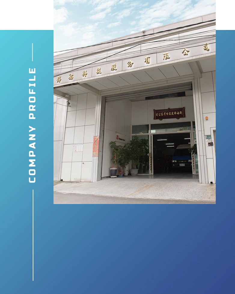
Evercom's company profile states that its business developed from OEM toward ODM and JDM, with collaboration beginning at the product design stage and continuing through testing and mass production. This type of early involvement is particularly useful when antenna behavior is highly dependent on the customer's complete device.
An antenna does not operate independently of the product around it. Ground plane size, enclosure material, display, battery, cable routing, metal brackets, heat sinks, and nearby antennas can alter tuning and radiation. An antenna that performs well as an isolated component may behave differently after installation.
Mechanical and industrial-design decisions should be reviewed before tooling or layout is frozen. A small change in antenna position or surrounding material may have a larger effect than selecting a higher nominal-gain specification.
Testing should follow an agreed plan and use a representative device configuration. Early prototypes are used to identify integration risk; approval samples should represent the intended materials, cable, connector, and assembly as closely as practical.

Test results should always be interpreted together with the test setup. Device revision, firmware, cable routing, mounting, fixture, and operating mode should be recorded so that later comparisons remain meaningful.
Technical approval is more than accepting a sample. The approved configuration should be identifiable and reproducible. A practical approval package may include the product drawing, material and appearance requirements, connector and cable definition, approved sample or sample code, inspection criteria, packaging requirements, and relevant test records.
Revision control is especially important in a custom antenna project because changes to the enclosure, PCB, battery, cable path, connector, adhesive, or material can affect performance or assembly. Both parties should agree on which changes require notification, re-evaluation, or a new approval. Purchasing, engineering, quality, and manufacturing teams should all reference the same revision.
A capable antenna partner should be evaluated on communication and engineering discipline as well as product range. Buyers should ask how requirements are reviewed, how prototypes and revisions are identified, what tests can be supported, how production changes are controlled, and how technical issues are escalated.
| RFQ category | Information to include | Why it matters |
|---|---|---|
| Application and radios | Device use, wireless standards, modules, target markets, and bands | Defines the required RF scope and regional coverage. |
| Mechanical constraints | Drawings, space, enclosure material, mounting, keep-out areas, and nearby components | Allows feasibility and integration risks to be reviewed. |
| Interface | Connector, cable, length, routing, polarity, and assembly direction | Prevents incompatible samples and unexpected loss. |
| Validation | Required measurements, device tests, environment, reports, and approval criteria | Creates a shared definition of completion. |
| Commercial plan | Prototype quantity, forecast, schedule, packaging, labeling, and delivery region | Supports a realistic quotation and production plan. |
No. A standard antenna may be suitable when its bands, dimensions, mounting, cable, connector, and performance in the final device meet the project requirements. Custom development is most useful when important constraints cannot be resolved with an existing product.
In a typical OEM project, the buyer owns a more complete design or specification and the supplier manufactures to the agreed definition. In an ODM project, the supplier contributes more product and engineering design based on the buyer's application requirements.
The enclosure, PCB, battery, display, cables, metal parts, and installation position can affect antenna tuning and radiation. Testing with a representative device provides more useful information than testing the antenna alone.
The approved antenna revision, drawing, materials, cable, connector, assembly, inspection criteria, packaging, and applicable test records should be clearly identified. Changes should follow an agreed review and notification process.
Send the application, required frequency bands, target markets, available space, enclosure information, mounting, connector, cable, validation expectations, sample quantity, forecast, and schedule. Mark fixed requirements and items that remain open for supplier recommendations.
OEM, ODM, and JDM are useful descriptions, but project success depends on clearly defined responsibilities, complete requirements, representative testing, controlled approval, and early RF-mechanical collaboration. Buyers who prepare system information before the first inquiry can receive more relevant proposals and reduce repeated sampling.
Learn more about Evercom's company and development background, browse the antenna product range, review new products, or revisit the antenna selection guide. For a project review, contact Evercom with your device, RF, mechanical, and schedule requirements.